Bcd excess converter code circuit logic digital [diagram] bcd adder circuit diagram Excess-3 adder subtractor
Solved Design an Excess-3 adder circuit that adds two valid | Chegg.com
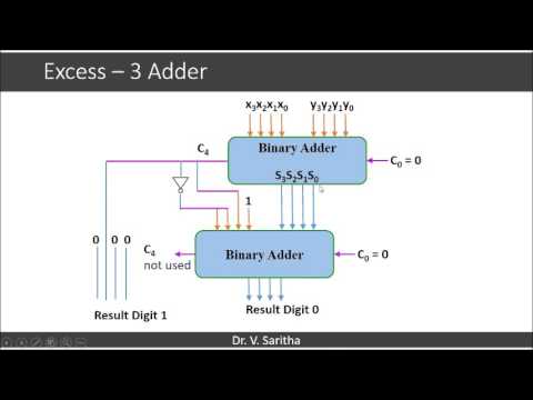
Excess 3 adder circuit diagram
[diagram] bcd to excess 3 logic diagram
Adder circuit truth logic xor sum adders gates ripple schematic binary theorycircuit rangkaian circuits transistor schematics dan pengertian kombinasi equationBcd to binary converter circuit diagram Bcd to excess 3 code converter digital logic circuit design downloadBcd adder schematic diagram.
Full adder circuit – how it worksDigital logic Excess 3 adder circuit diagramEmpower youth.

4-bit adder subtractor
Explain four-bit parallel adders with block diagram, and also explainSolved design an excess-3 adder circuit that adds two valid Bcd to excess 3 code converter using nand gates(project) ece419 digitalAdder excess binary construct bcd.
Excess 3 adder circuit diagramExcess 3 adder circuit diagram Excess 3 adder circuit diagramMake half and full adder without chips.

Full adder circuit and its construction
Lab 009 bcd to excess-3 codeExcess 3 adder circuit diagram Excess 3 adder circuit diagram4 bit bcd circuit diagram.
Excess 3 adder circuit diagramExcess bcd code circuit logic 8421 digital converters geeksforgeeks Excess 3 addition by parallel adder, combinational circuit in digitalHow to build a full adder.

8 bit full adder circuit diagram
Full adder equationAdder circuit truth logic gates binary circuits introduction equations Bcd to excess 3 code conversion » freak engineerAdder excess subtractor.
4 bit adder subtractor circuit diagram .